555 Timer Schematic / Astable Multivibrator using 555 Timer : The 555 ic timer circuit above shows a very straightforward design where the ic 555 forms the central controlling part of the circuit.
555 Timer Schematic / Astable Multivibrator using 555 Timer : The 555 ic timer circuit above shows a very straightforward design where the ic 555 forms the central controlling part of the circuit.. An arduino microcontroller is used to demonstrate usage. The 555 timer is a chip that can be us… Additional • timing from microseconds through hours terminals are provided for triggering or resetting if • operates in both astable and monostable modes desired. 555 timer circuits (133) browse through a total of 133 555 timer circuits and projects including the timer's datasheet. Derivatives provide two or four timing circuits in one package.it was commercialized in 1972 by signetics.
Its name is derived from three 5k ohm resistors ,connected in series used in it.the timer ic can produce required waveform accurately. Derivatives provide two or four timing circuits in one package.it was commercialized in 1972 by signetics. The 555 timer is probably one of the more versatile black box chips. A tutorial on how to make an adjustable delay timer circuit using 555 ic that can automatically turn on/off any output after a fixed duration. These on off intervals can be adjusted by varying the 555 timer output and number of counter outputs.
How to Build a 555 Timer Monostable Circuit from www.learningaboutelectronics.com Its name is derived from three 5k ohm resistors ,connected in series used in it.the timer ic can produce required waveform accurately. The output of the 555 stays high until (the 15 seconds) sending it low. The standard 555 timer ic is made of 2 diodes. A monostable 555 timer is required to produce a time delay within a circuit. 555 timer helpers schematic the addition of a capacitor to the trigger will not work for short output pulses as there is also a short delay in the recovery of the trigger terminal voltage. There are simple circuits for beginners and advanced engineers. 500ms is the same as saying 0.5s so by rearranging the formula above, we get the calculated value for the resistor, r as: This tutorial provides sample circuits to set up a 555 timer in monostable, astable, and bistable modes as well as an in depth discussion of how the 555 timer works and how to choose components to use with it.
The values of r1 and c1 determine how long the output will remain high.
The 555 timer is a simple integrated circuit that can be used to make many different electronic circuits. The 555 can be used to provide time delays, as an oscillator, and as a flip flop element. This pin connects to the negative side of the battery. 555 timer was first introduced by signetics corporation in 1971 as se555/ne555. The ic can operate in three different modes such as astable, monotstable and bistable, because of which it can be adapted into many types of circuit designs like time delay circuits, pulse generation circuit, oscillator circuit and much more. Here, with the help of the 555 timer ic, we are eliminating the need of manually switching on or off the device. A collection of 555 circuits using the 555 timer as an astable oscillator with different duty cycles. As discussed in the above section, the ic is in its standard monostable mode. These on off intervals can be adjusted by varying the 555 timer output and number of counter outputs. 555 timer circuits (133) browse through a total of 133 555 timer circuits and projects including the timer's datasheet. A tutorial on how to make an adjustable delay timer circuit using 555 ic that can automatically turn on/off any output after a fixed duration. The output voltage from the chip is around 1.5 v lower than vcc when high and around 0 v when low. The 555 timer delay before turn on circuit we will build is shown below.
Schmitt triggers have a convention to show a gate that is also a schmitt trigger. 555 timer circuits (133) browse through a total of 133 555 timer circuits and projects including the timer's datasheet. A tutorial on how to make an adjustable delay timer circuit using 555 ic that can automatically turn on/off any output after a fixed duration. The values of r1 and c1 determine how long the output will remain high. Each mode of operation indicates a circuit diagram and its output.
555 Timer Assembly Instructions | Synthrotek from www.synthrotek.com The 555 is also very versatile, and can be used. Being an integral part of electronics project, 555 timer ic is very often used in simple to complex electronics projects. An arduino microcontroller is used to demonstrate usage. Derivatives provide two or four timing circuits in one package.it was commercialized in 1972 by signetics. The second 555 timer helper will extend the timers output duration without having to use large values of r1 and/or c1. The 555 ic timer circuit above shows a very straightforward design where the ic 555 forms the central controlling part of the circuit. Using the 555 timer ic in special or unusual circuits. Simple 555 timer circuits & projects.
The 555 timer is probably one of the more versatile black box chips.
In this project, we are using 555 timer ic to create various timer circuit like 1 min timer circuit, 5 min timer circuit, 10 min timer circuit, and 15 min timer circuit. If a 10uf timing capacitor is used, calculate the value of the resistor required to produce a minimum output time delay of 500ms. Simple 555 timer circuits & projects. The values for r1, r2 and c1 configure the 555 timer to send the rst pin of the arduino low about every 15 seconds. The 555 timer is probably one of the more versatile black box chips. This circuit of this project makes the use of timer ic ne555 which produces a constant square pulse of a desired frequency. We connect a 100μf capacitor to the positive voltage supply and then to pin 2. The 555 ic timer circuit above shows a very straightforward design where the ic 555 forms the central controlling part of the circuit. 555 timer is an industrial standard ic existing from early days of ic. The 555 timer ic is an integrated circuit (chip) used in a variety of timer, delay, pulse generation, and oscillator applications. The output voltage from the chip is around 1.5 v lower than vcc when high and around 0 v when low. This circuit uses very basic components like 555 timer and 4017 counter. Circuits into the ever increasing ranks of timer users.
Also, 555 timer is used to generate an oscillating pulse. The above schematic shows the 555 timer bistable multivibrator circuit. The standard 555 timer ic is made of 2 diodes. In 2017, it was said over a billion 555 timers are produced. The 555 timer is a simple integrated circuit that can be used to make many different electronic circuits.
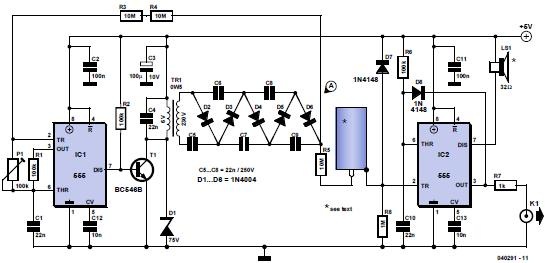
Making a Geiger counter with 555 timer IC - Electronics ... from www.electronics-lab.com This circuit of this project makes the use of timer ic ne555 which produces a constant square pulse of a desired frequency. In this project, we are using 555 timer ic to create various timer circuit like 1 min timer circuit, 5 min timer circuit, 10 min timer circuit, and 15 min timer circuit. The 555 timer is a simple integrated circuit that can be used to make many different electronic circuits. Once this switch is pushed, the circuit pulls its output to a. The 555 ic timer circuit above shows a very straightforward design where the ic 555 forms the central controlling part of the circuit. The circuits explained here are 10 best small timer circuits using the versatile chip ic 555, which generates predetermined time intervals in response to momentary input triggers. Let us discuss in detail about this circuit. 555 timer helpers schematic the addition of a capacitor to the trigger will not work for short output pulses as there is also a short delay in the recovery of the trigger terminal voltage.
The 555 timer is probably one of the more versatile black box chips.
The block diagram of a 555 timer is shown in the above figure. The above schematic shows the 555 timer bistable multivibrator circuit. The output of the 555 stays high until (the 15 seconds) sending it low. Here, with the help of the 555 timer ic, we are eliminating the need of manually switching on or off the device. As discussed in the above section, the ic is in its standard monostable mode. Circuits into the ever increasing ranks of timer users. The working modes of a 555 timer are astable, bistable, and monostable. Simple 555 timer circuits & projects. The 555 can be used to provide time delays, as an oscillator, and as a flip flop element. Adjustable on off timer(using 555 astable mode) in this circuit a timer with cyclic on off operations is designed. These on off intervals can be adjusted by varying the 555 timer output and number of counter outputs. 500ms is the same as saying 0.5s so by rearranging the formula above, we get the calculated value for the resistor, r as: We have seen in the last few tutorials that the 555 timer can be configured with externally connected components as multivibrators, oscillators and timers, with timing intervals ranging from a few microseconds to many hours.


0 Komentar